T. B. Reed and Ron Larson
*Presented at the "Developments in Thermochemical Biomass Conversion" Conference, Banff, Canada, 20-24 May, 1996.
Introduction -
A.The Problem
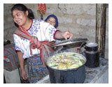
Since the beginning of civilization wood and biomass have been used for cooking. Over 2 billion people cook badly on inefficient wood stoves that waste wood, cause health problems and destroy the forest. Electricity, gas or liquid fuels are preferred for cooking - when they can be obtained, but they depend on having a suitable infrastructure and are often not available in developing countries. In the last few decades, many improved wood stoves have been developed (the Chula, the Hiko, the Maendeleo, the Kuni Mbili, etc.), but the new wood stoves are often more difficult to manufacture, often more heat goes to the stove than to the food, and they do not offer good control of cooking rate. They are not always accepted by the cooks for whom they are developed.[1] Because of the problems of wood cooking, people often cook over charcoal. However, charcoal manufacture is very wasteful of energy and very polluting, so the problems of the wood stove are externalized but not solved.
A.THE SOLUTION
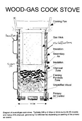
Gas is preferred for cooking wherever it is available. Gas can be made from wood and biomass in gasifiers developed in this century, but these gasifiers are generally too big for home use. A downdraft stove for domestic cooking is now being manufactured in China.[2] We have developed a new "inverted downdraft gasifier" stove shown in Fig. 1. It operates using only natural convection. The rate of gas production and heating is controlled by the primary air supply to the gasifier. As an option, the gasifier can make charcoal with a 20-25% yield. The wood-gas stove consists of an "inverted downdraft gasifier" (shown in Fig. 2) plus a burner to mix air and gas and burn cleanly (Fig. 3). These sections are discussed below. The stove has been started and operated indoors with no exhaust fans and no odor of burning wood. However, we believe that there is still much work to be done in optimizing the stove for various fuels, adapting it to various cooking situations and developing other uses. For that reason we are publishing our preliminary results and hope that others will help adapt these principles to improve world cooking and wood conservation.
I.CONSTRUCTION OF THE WOOD-GAS STOVE
A.The Inverted Downdraft Gasifier
Wood gasifiers can be classified as: Fixed bed (updraft and downdraft); and fluidized bed. Fluidized bed gasifiers Require high power input, and exact controls and are suitable only for large installations. Updraft gasifiers produce large amounts of tar while consuming the charcoal residue and are not suitable for cooking. Downdraft gasifiers in the 5-100 kW level were widely used in World War II for operating vehicles and trucks because of the relatively low tar levels. [3] In operation, air is drawn down through a bed of burning wood, consuming the volatiles. The resulting gas then passes over the resulting charcoal and is reduced to a low energy fuel gas. However, since hot gases naturally rise, it is necessary to supply power to draw the gases DOWN through the gasifier. In 1985 we developed the "inverted downdraft gasifier" (also called "upside downdraft, or pyrolysing gasifier) operating on natural draft. The name comes from the fact that the fuel charge is lit ON THE TOP, and forms a layer of charcoal there; the flaming pyrolysis zone is below that; the unburned fuel is on the bottom of the pile, and primary air for pyrolytic gasification enters at the bottom and moves UP, forming gas in the flaming pyrolysis zone, as shown in Fig. 2. At that time we built a clean, efficient stove using a jet of compressed air to mix secondary air with the gas and a venturi burner to hold the flame. However, developing country households typically do not have compressed air, so we began development of a natural draft, close coupled cooking gasifier. In 1991 we described a cooking stove based on the inverted downdraft gasifier with natural draft secondary air entering the gasifier above the charcoal zone. The combustion in this stove was relatively clean, but the poor air-gas mixing resulted in a unstable, partly yellow flame. The stove is marketed under the name "GAS-I-FIRE". [4]
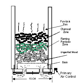
Fig. 2 - Inverted downdraft gasifier made from "riser sleeve", showing primary air inlet, fuel zone, flaming pyrolysis zone and charcoal zone
The inverted downdraft gasifier is operated in batch mode, appropriate for cooking meals. (The gasifier can also be operated continuously by addition of an auger feed for the fuel at the bottom and an auger to remove charcoal at the top. However, this complicates construction.) We have built several dozen gasifiers from tin cans, pails, stove pipes and "riser sleeves". We have operated gasifiers varying in size from 10 cm (4 in) to 25 cm (10 in) inside diameter. We have built several dozen burner combinations while looking for clean combustion from the burner. The simplest gasifiers are made from 2 lb coffee cans using a "church key" can opener to punch holes in the bottom. Heat losses are high in can stoves, but they are very simple to build. We use metal shears for cutting the metal parts, and sheet metal screws for outside attachments and burner and pan supports. "Riser sleeves" are particularly useful for construction of these stoves. They are made for use in casting molten iron and bronze, so are not affected by the temperatures involved in gasification and combustion. They are available in nominal 3 in to 6 in inside diameter in ½ in steps and in 6 to 10 in inside diameter in one inch steps. All stock sleeves are 30 cm (12 in) tall. As purchased, they are relatively soft and can be cut with saw or razor knife. However, they can also be "rigidized" by application of amorphous silica. They provide excellent insulation, and this is particularly important in small diameter gasifiers. 15 cm OD, 12.5 cm ID sleeves 30 cm tall capable of containing molten steel retail for about $3 in the U.S.[Riser] We believe that our stove can be built for under US$10 in the U.S. or developing countries. A major advantage of the inverted downdraft gasifier is that the rate of gas production depends on the amount of primary air admitted to the bottom. For this reason it is very important to put a tight sealing valve on the bottom which permits a wide range of air adjustments. A simple valve made from 24 gauge sheet metal is shown in Fig. 3.
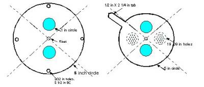
Fig. 3. Details of one type of air valve for coarse and fine control of primary air. We have also constructed very satisfactory stoves from tin cans with riser sleeve liners. Use of the outer can permits addition of simple handles to the gasifier and burner sections.
A.The Wood-Gas Burner
Many burner designs have been tested for the wood-gasifier. The simplest is a series of holes in the gasifier above the level of the charcoal (as discussed for the Hottenroth stove above). However, this does not give good mixing and complete combustion. A better burner consists of a second can mounted a distance of about 1 cm above the first can. Air enters through this annular ring and mixes with the gas and burns. We have developed a "blue flame" burner (Fig. 4), using a "gas wick" to burn the gas in a very clean manner. In order for the amount of combustion products to have maximum draft, the area must be adjusted. (Conventional gas stoves typically have a ring of fire about 70-120 mm in diameter and about 5 mm across the ring.)
A.Wood-gas Stove Fuels
We have successfully gasified 1-3 cm softwood chips, 1-2 X 10 cm hardwood sticks and 5 mm diameter canes from bushes. The hard woods produce a relatively dense charcoal; the softwoods produce a lighter more friable charcoal.
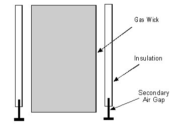
Fig. 4. Annular burner for "blue flame" combustion of wood gas using a "gas wick"
Much of the tests made on the stove used 2 X 1 X ½ cm air dry (about 7% moisture in Denver) Aspen chips in order to have reproducibility . However, we have find the stove operates at least as well on sticks standing vertically. Smaller fuel particles do not permit sufficient air to pass through the bed, and so we have not had success gasifying 0.5 mm wood pellets or corn.
A.Wood-Gas Stove Operation
The gasifier is filled to within 2 cm of the top. It is desirable to have the fire spread rapidly laterally across the surface to provide gas over the whole area, so an easily combustible material, such as dry pine needles, fibers soaked in animal fat or vegetable grease or other "tinder" is placed on top. The tinder is ignited in several places with a match and allowed to burn for a minute or so. When a stable flame is established all around, the burner is placed slowly on top of the gasifier to permit the inside surfaces to become hot. A continuous (smokeless) blue flame was established in 2 minutes and ran continuously for 37 minutes when it went out in Run # 5, p. 92, Book II. The weight of stove (plus the change of weight of 1 liter of water in a pan, added at minute 11) is shown in Fig. 5. It is seen that the stove burned about 12 g/min with full primary air. At 20 min primary air was turned to 20 % and the stove then burned at a rate of 4.5 g/min. 155 g of charcoal remained at the end of the run.
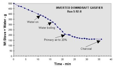
Fig. 5. Typical inverted downdraft gasifier run, No. 5, p. 92, Book II, showing initial stable combustion at 12 g/min, pan on at 11 min, water boiling at 19 min, primary air turned to 20% for simmering at 20 min, and a yield of 150 g charcoal
A.Wood-gas stove emissions
Wood-gas cooking has very low emissions and can be operated indoors with proper precautions once established. However, if the fire is extinguished for any reason the production of smoke and CO continues, so that it is important to be able to extinguish it completely or take it outside. The stove is difficult to extinguish and the bottom air valve must be AIR TIGHT. A pan of water can then be placed on top of the gasifier and there will be no subsequent production of smoke. In a preliminary measurement we have measured the CO level 80 cm above the stove as 22 PPM. The level in the room had no measurable rise. During gasification of wood, if the fire is extinguished the acrid tars in the wood make it unlikely that one would breathe too much CO. However, after the wood is gasified the stove contains hot charcoal and so can be a major source of CO. For this reason it is important to either continue to burn the charcoal or to cut off ALL air to the stove and preserve the charcoal as discussed below.
A.Charcoal manufacture
We find that in a typical run we have a charcoal yield of 10-15% (dry basis). If it is desired to keep the charcoal, it is important that it be possible to close off ALL air to the charcoal after the volatiles are consumed. The valve shown in Fig. 3 should be made of relatively stiff metal to permit a tight closure. The top of the gasifier is closed with a pan over the top. In addition it is useful to spray water on the top pan and the lower parts of the stove to cool it down to prevent continuing oxidation of the charcoal.
I.STOVE TESTING
Fuel consumption in most of the development runs on the stove were monitored by placing the stove, chimney-burner etc. on a digital balance and recording the weight every minute during the run. In this way it was possible to determine the rate of consumption as a function of primary air setting. A typical chart is shown in Fig. 5. A mass-energy balance was made in a small gasifier connected to a flowmeter and an integrating total flow (Singer) meter. The flow was fixed at 10 scfh from 3 to 30 minutes. The gas was burned in a 10-15 cm high diffusion flame above the gasifier. 135 g of aspen chips 7.8% moisture produced 26.3 g of charcoal (yield =19.5%, 24.2% dry basis). The total air flow was 160 g of air or 30.8 g O2. The mass and energy balances are then:
The air/fuel ratio is 1.28. The air/fuel ratio for complete combustion is 6.36, so the equivalence ratio (air consumed/air required for complete combustion) for this test is 0.20 (compared to .25 for equilibrium gasification of dry wood. The gas probably has a higher energy content than conventional gas because no air is required for char conversion. The hat gas energy content will be particularly high because it contains the sensible heat and volatiles as well as the gas.
I.PRELIMINARY MODELLING OF THE WOOD-GAS STOVE
A major advantage of the wood-gas stove is that the gasifier section is stratified and so can be modeled using a simple one dimensional flow scheme. We modeled the conventional stratified downdraft gasifier ("open-top" gasifier, "topless gasifier") and are using the same approach for the inverted downdraft gasifier. The following guidelines are useful for predicting fuel consumption, burn time, stove power and stove size.
Power: The heat content of the gas is ~ 18kJ/g, so consumption of 4-10 g/m produces 1.2-3.0 kWt . (U.S. Electric stoves usually have a 1.5 and a 2.5 kW burner.). The production rate is approximately proportional to cross sectional area. Larger cooking jobs will require larger stoves
Primary Air: The heat for pyrolysis is about 2,000 j/g. Pyrolysis requires 2/3 g air/per g wood or 600 ml air/g wood. 3 kWt requires 6 l air/min
Primary draft: The pyrolysis gas temperature is about 500 °C and so generates a draft of 100 mm-water pressure
Secondary draft: The gas flow around the gas wick is quite complex and work is in progress on calculation of the gas and air flow
I.Conclusions
The wood-gas stove has been started and operated indoors with no exhaust fans and no odor of burning wood. However, we believe that there is still much work to be done in optimizing the stove for various fuels, determining the effect of moisture, adapting it to various cooking situations and developing other uses. For that reason we are publishing our preliminary results here and hope that others will help adapt these principles to improve world cooking and wood conservation.
I.References
[Gao, 1992] Gao Xiansheng, "Biomass Domestic Cooking Gasifier Stove", in "Advances in Thermochemical Biomass Conversion" Conference, Interlaken, Switzerland, A. Bridgwater, Ed., 1992.
[Handbook, 1987] Reed, T. B. and Das, A., "Handbook Of Biomass Downdraft Gasifier Engine Systems", (SERI-1988) BEF Press, Golden, CO. . [Hottenroth, 1992] Hottenroth, F,"Gas-I-Fire Stove by ZMART STOVES", Z.Z.Corp., 10806 Kaylor Street, Los Alimitos, CA. 90720. [LaFontaine, 1991] La Fontaine, H. and Reed, T. B., "An Inverted Downdraft Wood-Gas Stove and Charcoal Producer", in Energy from Biomass and Wastes XV, D. Klass, Ed., Washington, D. C.,
[Riser, 1996] Kalmin 70 riser sleeves, obtained from United Western Supply Co., 4401 E 46th Ave., Denver CO 80216-3261.
[Wood Stove Refs] See for instance:
[Kammen, D. M.] Kammen, D. M., "Cookstoves for the Developing World", Scientific American, July, 1995, p. 72.
WOODHEAT FOR COOKING (eds:K.Krishna Prasad and P.Verhaart), Indian Academy of Sciences, 1983.
Many papers in Publications of Stockholm Envirnment Institue, SEI, Box 2142, S-103 14 Stockholm, Sweden
Many Papers in "Boiling Point", Intertechnology Development Group, (ITDG) Myson House, Railway Terrace, Rugby, CV21 3HT, UK. (Tel 0788 560631) or the German Assocation for Technical Cooperation (GATT).
Baldwin, Sam, "Biomass Stoves" Engineering Design, Development and Dissemination, Volunteers in Technological Development (VITA), Arlington, VA. 1987.
[Barnes, F., 1994] Barnes, F. Openshaw, K., Smith, K. and van der Plas, R., "What Makes People Cook with Improved Biomass Stoves", World Bank Technical Paper No. 242, Energy Series, 1994.Air Jordan 1